Using Arduino Uno R3 to receive RC receiver PWM signal and turn on/off switch to control any appliance. Depending on the channels on the RC receiver used, one controller can control many appliances.
Sketch
#define pwmIn 3 // connect RC receiver signal output to Arduino Uno D3
#define onOffValue 1700 // pwm value to turn on/off switch
int data1;
void setup () {
pinMode (pwmIn, INPUT);
pinMode (13, OUTPUT);
}
void loop () {
data1 = pulseIn(pwmIn, HIGH);
if (data1> onOffValue) {digitalWrite (13, HIGH);} else {digitalWrite (13, LOW);}
delay (10);
}
2020/07/12
Arduino Uno R3 Displaying RC Receiver PWM Signal Output
Connecting RC Receiver channel signal output to Arduino Uno R3 D3, compiling, uploading the sketch and displaying the pwm value in Serial Monitor.
Sketch
#define pwmIn 3 // connect RC receiver signal output to Arduino Uno D3
int signal;
void setup() {
pinMode(pwmIn,INPUT);
Serial.begin(115200);
}
void loop() {
signal = pulseIn(pwmIn,HIGH);
Serial.println(signal);
delay(10);
}
Sketch
#define pwmIn 3 // connect RC receiver signal output to Arduino Uno D3
int signal;
void setup() {
pinMode(pwmIn,INPUT);
Serial.begin(115200);
}
void loop() {
signal = pulseIn(pwmIn,HIGH);
Serial.println(signal);
delay(10);
}
2019/09/14
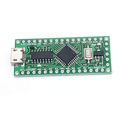
LGT8F328P LQFP32 - An ATMega328P Arduino Nano V3.0 Compatible Development Board
LGT8F328P contains DAC converter, High current push-pull PWM, PWM dead zone control, Stacking expansion system, Computing Accelerometer (DSC), internal voltage reference should be improved up to 0.5% instead of 1.5%. Maximal clock speed should be up to 32 MHz (16 MHz ATMega328P).
Github of LogicGreen is here https://github.com/LGTMCU/Larduino_HSP
Other informaction and specification you can find on https://www.electrodragon.com/w/Logicgreen
and also on http://www.ocrobot.com/doku.php?id=ocrobot:alpha:8f328p-u:main
2019/07/20
MakerRemote Mower: Sketch For Radio Frequency Remote Controlling A Mower Or Car
The sketch is used to control the direction the radio frequency controlled mower or car. The message sent can be monitored by SimpleReceiveLCD on May. 11, 2014.
Sketch
//File Name: MakerRemoteMowerDirectionSendOneTimeV10
// Modified by Befun Hung on Jul. 16, 2019
// Blink led on time after sending direction character (one character)
// The direction character may be one of 0-9, * and #
// The direction character is designed as
// 2, forward, both left and right wheel forward
// 4, left, right wheel forward and left wheel backward
// 6, right, left wheel forward and right wheel backward
// 8, backward, both left and right wheel backward
// 1, forward left, right wheel forward and left wheel stop
// 3, forward right, left wheel forward and right wheel stop
// 7, backward left, right wheel backward and left wheel stop
// 9, backward right, left wheel backward and right wheel stop
// 5, stop both left and right wheels
// 0, do nothing
// *, turn on mower motor
// #, turn off mower motor
// The sketch is tested and comfirmed with only one direction character received
//
// Modified by Befun Hung on Oct. 28, 2014
// Blink led after sending message to notice user 5 times
#include <Keypad.h>
#include <VirtualWire.h>
#define maxLength 1 // maxLength 3 changed to 1
const byte ROWS = 4; // four rows
const byte COLS = 3; // three columns
char keys[ROWS][COLS] = {
{'1','2','3'},
{'4','5','6'},
{'7','8','9'},
{'*','0','#'}
};
// Connect keypad ROW0, ROW1, ROW2 and ROW3 to these Arduino pins.
byte rowPins[ROWS] = {5, 4, 3, 2};
// Connect keypad COL0, COL1 and COL2 to these Arduino pins.
byte colPins[COLS] = {8, 7, 6}; // connect to the column pinouts of the keypad
char keyins[maxLength+1] = "";
int i=0, j=0, sendTimes=1; // sendTimes 5 changed to 1
int led=13;
Keypad keypad = Keypad( makeKeymap(keys), rowPins, colPins, ROWS, COLS );
void setup() {
Serial.begin(9600);
// Initialize the IO and ISR
vw_setup(2000); // Bits per sec
Serial.println("Ready!");
pinMode(led, OUTPUT);
}
void loop() {
char key = keypad.getKey();
if (key) {
Serial.print(key);
keyins[i] = key;
i++;
if (i == maxLength) {
for (j=0;j<sendTimes;j++) {
Serial.println();
send(keyins);
digitalWrite(led, HIGH);
delay(20);
digitalWrite(led, LOW);
delay(20);
}
i = 0;
}
}
}
void send(char *message)
{
vw_send((uint8_t *)message, strlen(message));
vw_wait_tx(); // Wait until the whole message is gone
}
2018/04/02
A Simple MQTT Websocket Client
The code is based on wbesockets-3.html by Steve Cope on "Using The JavaScript MQTT Client With Websockets" combines code by weldmich on "Developing MQTT Client" and web page on "How to program messaging apps in JavaScript" of IBM Knowledge Center. With the HTML file, anyone can uses any web browser supporting websockets to communicate with any MQTT IoT device without the need to download and use any mqtt client app. For example, I can use google chrome opening the HTML file to control my homebrew web switch MakerSwitch Tail WiFi.
Screen Capture
 HTML File
<?xml version="1.0" encoding="UTF-8" standalone="no"?>
<!DOCTYPE html PUBLIC "-//W3C//DTD XHTML 1.0 Transitional//EN" "http://www.w3.org/TR/xhtml1/DTD/xhtml1-transitional.dtd">
<html xmlns="http://www.w3.org/1999/xhtml">
<style>
#messages
{
background-color:yellow;
font-size:3;
font-weight:bold;
line-height:140%;
}
#status
{
background-color:red;
font-size:4;
font-weight:bold;
color:white;
line-height:140%;
}
</style>
<head>
<meta charset="utf-8">
<meta name="viewport" content="width=device-width, initial-scale=1.0">
<title>MQTT Websocket Client</title>
<script src="https://cdnjs.cloudflare.com/ajax/libs/paho-mqtt/1.0.1/mqttws31.js" type="text/javascript"></script>
<script type = "text/javascript"
src = "https://ajax.googleapis.com/ajax/libs/jquery/2.1.3/jquery.min.js"></script>
<script type = "text/javascript">
function onConnectionLost(){
console.log("connection lost");
document.getElementById("status").innerHTML = "Connection Lost";
document.getElementById("messages").innerHTML ="Connection Lost";
connected_flag=0;
}
function onFailure(message) {
console.log("Failed");
document.getElementById("messages").innerHTML = "Connection Failed- Retrying";
setTimeout(MQTTconnect, reconnectTimeout);
}
function onMessageArrived(r_message){
out_msg="Message received: \""+r_message.payloadString;
out_msg=out_msg+"\" from Topic: "+r_message.destinationName;
//console.log("Message received ",r_message.payloadString);
console.log(out_msg);
document.getElementById("messages").innerHTML =out_msg;
}
function onConnected(recon,url){
console.log(" in onConnected " +reconn);
}
function onConnect() {
// Once a connection has been made, make a subscription and send a message.
document.getElementById("messages").innerHTML ="Connected to "+host +"on port "+port;
connected_flag=1;
document.getElementById("status").innerHTML = "Connected";
console.log("on Connect "+connected_flag);
}
function MQTTconnect() {
document.getElementById("messages").innerHTML ="";
var s = document.forms["connform"]["server"].value;
var p = document.forms["connform"]["port"].value;
if (p!="")
{
port=parseInt(p);
}
if (s!="")
{
host=s;
}
console.log("connecting to "+ host +" "+ port);
mqtt = new Paho.MQTT.Client(host,port,"clientjsaaa");
//document.write("connecting to "+ host);
var options = {
timeout: 3,
onSuccess: onConnect,
onFailure: onFailure,
};
mqtt.onConnectionLost = onConnectionLost;
mqtt.onMessageArrived = onMessageArrived;
mqtt.onConnected = onConnected;
mqtt.connect(options);
return false;
}
function sub_topics(){
document.getElementById("messages").innerHTML ="";
if (connected_flag==0){
out_msg="<b>Not Connected so can't subscribe</b>";
console.log(out_msg);
document.getElementById("messages").innerHTML = out_msg;
return false;
}
var stopic= document.forms["subs"]["Stopic"].value;
var qos = parseInt($('#subQos option:selected').val());
console.log("Subscribing to topic "+stopic+" with Qos "+qos);
mqtt.subscribe(stopic, {qos: qos});
return false;
}
function send_message(){
document.getElementById("messages").innerHTML ="";
if (connected_flag==0){
out_msg="<b>Not Connected so can't send</b>";
console.log(out_msg);
document.getElementById("messages").innerHTML = out_msg;
return false;
}
var msg = document.forms["smessage"]["message"].value;
console.log(msg);
var topic = document.forms["smessage"]["Ptopic"].value;
var qos = parseInt($('#pubQos option:selected').val());
var retain = $('#toRetain').is(':checked');
message = new Paho.MQTT.Message(msg);
if (topic=="")
message.destinationName = "test-topic";
else
message.destinationName = topic;
message.qos = qos;
message.retained = retain;
console.log("Published to topic "+topic+" with Qos "+qos);
mqtt.send(message);
return false;
}
</script>
</head>
<body>
<h1>MQTT Websocket Client</h1>
<script type = "text/javascript">
//ll
</script>
<script>
var connected_flag=0
var mqtt;
var reconnectTimeout = 2000;
var host="broker.mqttdashboard.com";
var port=8000;
</script>
<div id="status">Connection Status: Not Connected</div>
<form name="connform" action="" onsubmit="return MQTTconnect()">
<fieldset>
<legend id="Connect">Connect</legend>
Server: <input type="text" id="broker" name="server" placeholder="broker.mqttdashboard.com">
Port: <input type="text" id="port" name="port" placeholder="8000">
<input type="submit" value="Connect">
</fieldset>
</form>
<form name="smessage" action="" onsubmit="return send_message()">
<fieldset>
<legend id="Publish">Publish</legend>
Topic: <input type="text" id="pubTopic" name="Ptopic">
Message: <input type="text" id="payload" name="message">
<select id="pubQos">
<option value="Qos" disabled>Qos</option>
<option value="0">0</option>
<option value="1" selected>1</option>
<option value="2">2</option>
</select>
<label>Retain</label>
<input id="toRetain" type="checkbox">
<input type="submit" value="Publish">
</fieldset>
</form>
<form name="subs" action="" onsubmit="return sub_topics()">
<fieldset>
<legend id="Subscribe">Subcribe</legend>
Topic: <input type="text" id="subTopic" name="Stopic">
<select id="subQos">
<option value="Qos" disabled>Qos</option>
<option value="0">0</option>
<option value="1" selected>1</option>
<option value="2">2</option>
</select>
<input type="submit" value="Subscribe">
</fieldset>
</form>
<p id="messages"></p>
</body>
</html>
Screen Capture

<?xml version="1.0" encoding="UTF-8" standalone="no"?>
<!DOCTYPE html PUBLIC "-//W3C//DTD XHTML 1.0 Transitional//EN" "http://www.w3.org/TR/xhtml1/DTD/xhtml1-transitional.dtd">
<html xmlns="http://www.w3.org/1999/xhtml">
<style>
#messages
{
background-color:yellow;
font-size:3;
font-weight:bold;
line-height:140%;
}
#status
{
background-color:red;
font-size:4;
font-weight:bold;
color:white;
line-height:140%;
}
</style>
<head>
<meta charset="utf-8">
<meta name="viewport" content="width=device-width, initial-scale=1.0">
<title>MQTT Websocket Client</title>
<script src="https://cdnjs.cloudflare.com/ajax/libs/paho-mqtt/1.0.1/mqttws31.js" type="text/javascript"></script>
<script type = "text/javascript"
src = "https://ajax.googleapis.com/ajax/libs/jquery/2.1.3/jquery.min.js"></script>
<script type = "text/javascript">
function onConnectionLost(){
console.log("connection lost");
document.getElementById("status").innerHTML = "Connection Lost";
document.getElementById("messages").innerHTML ="Connection Lost";
connected_flag=0;
}
function onFailure(message) {
console.log("Failed");
document.getElementById("messages").innerHTML = "Connection Failed- Retrying";
setTimeout(MQTTconnect, reconnectTimeout);
}
function onMessageArrived(r_message){
out_msg="Message received: \""+r_message.payloadString;
out_msg=out_msg+"\" from Topic: "+r_message.destinationName;
//console.log("Message received ",r_message.payloadString);
console.log(out_msg);
document.getElementById("messages").innerHTML =out_msg;
}
function onConnected(recon,url){
console.log(" in onConnected " +reconn);
}
function onConnect() {
// Once a connection has been made, make a subscription and send a message.
document.getElementById("messages").innerHTML ="Connected to "+host +"on port "+port;
connected_flag=1;
document.getElementById("status").innerHTML = "Connected";
console.log("on Connect "+connected_flag);
}
function MQTTconnect() {
document.getElementById("messages").innerHTML ="";
var s = document.forms["connform"]["server"].value;
var p = document.forms["connform"]["port"].value;
if (p!="")
{
port=parseInt(p);
}
if (s!="")
{
host=s;
}
console.log("connecting to "+ host +" "+ port);
mqtt = new Paho.MQTT.Client(host,port,"clientjsaaa");
//document.write("connecting to "+ host);
var options = {
timeout: 3,
onSuccess: onConnect,
onFailure: onFailure,
};
mqtt.onConnectionLost = onConnectionLost;
mqtt.onMessageArrived = onMessageArrived;
mqtt.onConnected = onConnected;
mqtt.connect(options);
return false;
}
function sub_topics(){
document.getElementById("messages").innerHTML ="";
if (connected_flag==0){
out_msg="<b>Not Connected so can't subscribe</b>";
console.log(out_msg);
document.getElementById("messages").innerHTML = out_msg;
return false;
}
var stopic= document.forms["subs"]["Stopic"].value;
var qos = parseInt($('#subQos option:selected').val());
console.log("Subscribing to topic "+stopic+" with Qos "+qos);
mqtt.subscribe(stopic, {qos: qos});
return false;
}
function send_message(){
document.getElementById("messages").innerHTML ="";
if (connected_flag==0){
out_msg="<b>Not Connected so can't send</b>";
console.log(out_msg);
document.getElementById("messages").innerHTML = out_msg;
return false;
}
var msg = document.forms["smessage"]["message"].value;
console.log(msg);
var topic = document.forms["smessage"]["Ptopic"].value;
var qos = parseInt($('#pubQos option:selected').val());
var retain = $('#toRetain').is(':checked');
message = new Paho.MQTT.Message(msg);
if (topic=="")
message.destinationName = "test-topic";
else
message.destinationName = topic;
message.qos = qos;
message.retained = retain;
console.log("Published to topic "+topic+" with Qos "+qos);
mqtt.send(message);
return false;
}
</script>
</head>
<body>
<h1>MQTT Websocket Client</h1>
<script type = "text/javascript">
//ll
</script>
<script>
var connected_flag=0
var mqtt;
var reconnectTimeout = 2000;
var host="broker.mqttdashboard.com";
var port=8000;
</script>
<div id="status">Connection Status: Not Connected</div>
<form name="connform" action="" onsubmit="return MQTTconnect()">
<fieldset>
<legend id="Connect">Connect</legend>
Server: <input type="text" id="broker" name="server" placeholder="broker.mqttdashboard.com">
Port: <input type="text" id="port" name="port" placeholder="8000">
<input type="submit" value="Connect">
</fieldset>
</form>
<form name="smessage" action="" onsubmit="return send_message()">
<fieldset>
<legend id="Publish">Publish</legend>
Topic: <input type="text" id="pubTopic" name="Ptopic">
Message: <input type="text" id="payload" name="message">
<select id="pubQos">
<option value="Qos" disabled>Qos</option>
<option value="0">0</option>
<option value="1" selected>1</option>
<option value="2">2</option>
</select>
<label>Retain</label>
<input id="toRetain" type="checkbox">
<input type="submit" value="Publish">
</fieldset>
</form>
<form name="subs" action="" onsubmit="return sub_topics()">
<fieldset>
<legend id="Subscribe">Subcribe</legend>
Topic: <input type="text" id="subTopic" name="Stopic">
<select id="subQos">
<option value="Qos" disabled>Qos</option>
<option value="0">0</option>
<option value="1" selected>1</option>
<option value="2">2</option>
</select>
<input type="submit" value="Subscribe">
</fieldset>
</form>
<p id="messages"></p>
</body>
</html>
2017/12/27
Display Temperature on 8-digit 7-segment Max7219 LED Display using DS18B20
Photo

Sketch
/*
pin 13 (D7) is connected to the DataIn
pin 14 (D5) is connected to the CLK
pin 15 (D8) is connected to LOAD
Modified by Befun Hung on Mar. 26, 2017
to correct errors in comments and data displayed
Modified by Befun Hung on Mar. 27, 2017
to add and correct errors in printNumber() by circuits4you.com
Modified by Befun Hung on Mar. 30, 2017
to display temperature to 8-digits 7-segment module
*/
// 匯入程式庫標頭檔
#include <OneWire.h>
#include <DallasTemperature.h>
#include "LedControl.h"
#define DIN 13
#define CLK 14
#define LOAD 15
#define lowLimit 0.0
#define upLimit 37.3
LedControl lc=LedControl(DIN,CLK,LOAD,1);
// Arduino數位腳位2接到1-Wire裝置
#define ONE_WIRE_BUS D4
float myTemp;
long dispTemp;
// 運用程式庫建立物件
OneWire oneWire(ONE_WIRE_BUS);
DallasTemperature sensors(&oneWire);
void setup(void)
{
Serial.begin(115200);
Serial.println("Temperature Sensor");
// 初始化
sensors.begin();
// Initialize the MAX7219
// Serial.println("14CORE TEST CODE FOR LED MAX7219 LED TUBE");
// Serial.println(" --- Modified by Befun Hung on Mar. 26, 2017");
lc.shutdown(0,false); // To Enable the Display
lc.setIntensity(0,7); // To set the brightness level (0 is min, 15 is max)
lc.clearDisplay(0); // To Clear the display register
}
void loop(void)
{
// 要求匯流排上的所有感測器進行溫度轉換(不過我只有一個)
sensors.requestTemperatures();
// 取得溫度讀數(攝氏)並輸出,
// 參數0代表匯流排上第0個1-Wire裝置
// Serial.println(sensors.getTempCByIndex(0));
myTemp = (sensors.getTempCByIndex(0));
if (myTemp<lowLimit) {myTemp=lowLimit;}
if (myTemp>upLimit) {myTemp=upLimit;}
Serial.print(myTemp);
Serial.print(" C, ");
dispTemp = (long) round(myTemp * 10);
printC(dispTemp);
Serial.print(DallasTemperature::toFahrenheit(myTemp));
Serial.println(" F");
dispTemp = (long) round(DallasTemperature::toFahrenheit(myTemp) * 10);
printF(dispTemp);
delay(1000);
}
void printC( long v)
{
// Variable value digit
int digito6;
int digito7;
int digito8;
// Calculate the value of each digit
digito6 = (v % 10) ;
digito7 = (v / 10 )% 10 ;
digito8 = (v / 100 )% 10 ;
// Display the value of each digit in the display
lc.setDigit ( 0 , 7 , (byte) digito8, false);
lc.setDigit ( 0 , 6 , (byte) digito7, true);
lc.setDigit ( 0 , 5 , (byte) digito6, false);
lc.setRow(0, 4, B1001110);
}
void printF( long v)
{
// Variable value digit
int digito2;
int digito3;
int digito4;
// Calculate the value of each digit
digito2 = (v % 10) ;
digito3 = (v / 10 )% 10 ;
digito4 = (v / 100 )% 10 ;
// Display the value of each digit in the display
lc.setDigit ( 0 , 3 , (byte) digito4, false);
lc.setDigit ( 0 , 2 , (byte) digito3, true);
lc.setDigit ( 0 , 1 , (byte) digito2, false);
lc.setRow(0, 0, B1000111);
}
2017/11/06
GPS Synchronized RTC Clock
/*
* BuildAGPSControlledClock20171106.ino modified by Befun Hung
* -----------------------------------------------------------
* MyFeatherGPS.ino
*
* GPS-driven, digital clock with local and UTC time on 7-segment LED display.
*
* Author: Bruce E. Hall, W8BH
* Date: 01 May 2016
* Hardware: ATMEL 32u4 microcontroller on Adafruit "Feather" board
* Maxim DS 3212 real-time-clock on Adafruit Featherwing
* 4-digit 7-segment displays mounted on Adafruit I2C backpacks
* GPS module (Adafruit Ultimate GPS or UBLOX Neo-6M module)
* Software: Arduino 1.6.5
* Code size: about 17200 bytes
*
* The system keeps time in UTC, supplied by GPS and/or RTC when GPS is unavailable.
* Local time automatically tracks daylight saving time for selected time zone.
* USB serial port outputs time and GPS/RTC status messages.
* Dual display (local & UTC) very handy for a ham radio shack.
*
*/
#include <TimeLib.h> // github.com/PaulStoffregen/Time
#include <TinyGPS.h> // arduiniana.org/libraries/TinyGPS/
#include <Wire.h> // needed for I2C
#include <SoftwareSerial.h>
#include <DS1307RTC.h> // github.com/PaulStoffregen/DS1307RTC
#define TIME_SYNC_INTERVAL 180 // 180 seconds = 3 min between GPS time sync attempts
#define CYCLES_PER_RTC_SYNC 20 // 20 cycles = 1 hr between gps->rtc sync
#define RXPin 2
#define TXPin 3
#define ConsoleBaud 115200
#define GPSBaud 9600
// #define SerialGPS Serial1 // use hardware UART on 32u4 Feather
SoftwareSerial SerialGPS(RXPin, TXPin);
// Select timeZone offset from UTC:
const int timeZone = 8; // Taipei, Taiwan
TinyGPS gps; // gps string-parser object
time_t prevDisplay = 0; // when the digital clock was displayed
int cyclesUntilSync = 0; // counts number of cycles until RTC sync
time_t dstStart = 0; // start of DST in unix time
time_t dstEnd = 0; // end of DST in unix time
bool gpsLocked = false; // indicates recent sync with GPS
int currentYear = 0; // used for DST
void setup()
{
Serial.begin(ConsoleBaud); // start USB serial output
SerialGPS.begin(GPSBaud); // open UART connection to GPS
//manualTimeSet(); // allow temporary time setting before gps kicks in
setSyncProvider(timeSync); // specify time setting routine
setSyncInterval(TIME_SYNC_INTERVAL); // periodically get time from gps/rtc
}
//
// Here are the basic clock routines:
// "Loop" updates the display when a new time is available
// "TimeSync" keeps system time in UTC, and updates it with GPS data.
// If GPS is unavailable, time is updated from RTC chip instead.
//
void loop()
{
while (SerialGPS.available()) // look for GPS data on serial port
{
int c=SerialGPS.read(); // get one character at a time
gps.encode(c); // and feed it to gps parser
}
if (timeStatus()!= timeNotSet) // wait until time is set by sync routine
{
if (now() != prevDisplay) // dont update display until time changes
{
prevDisplay = now(); // save current time
updateDST(); // check DST status
displayLocalTime(); // show local time on LEDs
displayUTC(); // show UTC time on LEDs
printTime(prevDisplay); // send time to USB serial port
}
}
}
time_t timeSync()
// will change global variable "gpsLocked" according to ability to sync with GPS
// returns time as UTC
{
tmElements_t tm;
time_t t = 0;
int yr;
unsigned long fixAge;
gpsLocked = false; // assume failure to read GPS
gps.crack_datetime(&yr, &tm.Month, &tm.Day, // get UTC time from GPS
&tm.Hour, &tm.Minute, &tm.Second,
NULL, &fixAge);
if (fixAge==TinyGPS::GPS_INVALID_FIX_TIME) // GPS online but no satellite fix
{
Serial.println("\nNo GPS fix, using RTC");
t = RTC.get(); // ...so get from RTC instead
}
else if (fixAge > 2000) // GPS is offline
{
Serial.println("\nGPS offline, using RTC");
t = RTC.get(); // ...so get from RTC instead
}
else // GPS time is good
{
gpsLocked = true; // flag success
tm.Year = yr-1970; // convert calendar years to unix years
Serial.print("\nGPS time OK, ");
Serial.print(gps.satellites());
Serial.print(" sats. ");
if (cyclesUntilSync <=0) // time to update RTC yet?
{
if (RTC.write(tm)) // update real-time clock chip
Serial.print("RTC updated.");
else Serial.print("RTC update failed.");
cyclesUntilSync = CYCLES_PER_RTC_SYNC; // reset counter
}
Serial.println();
t = makeTime(tm); // convert to time_t
}
cyclesUntilSync --; // count-down another cycle
return t; // return unix time in UTC
}
void manualTimeSet()
// Use this routine to manually set the clock to a specific UTC time.
// Set each tm element to desired value
// Since time is automatic set from gps, this routine is mainly for debugging
{
tmElements_t tm;
tm.Year = 2016 - 1970; // Year in unix years
tm.Month = 11;
tm.Day = 6;
tm.Hour = 5;
tm.Minute = 59;
tm.Second = 30;
RTC.write(tm); // set RTC to desired time
}
//
// The following routines support automatic daylight saving time adjustment
//
// Daylight Saving Time constants:
// Please set according to current DST transition times
//
// define DST start value same as end value to disable DST time
//
#define DST_START_WEEK 2 // Second Sunday
#define DST_START_MONTH 3 // in March
#define DST_START_HOUR 7 // at 2AM EST = 0700 UTC
#define DST_END_WEEK 1 // First Sunday
#define DST_END_MONTH 11 // in November
#define DST_END_HOUR 6 // at 2AM EDT = 0600 UTC
time_t timeChange(int hr, int wk, int mo, int yr)
// returns unix time of DST transition according to hr, wk, mo, and yr
// Routine first calculates time on first day of month, at specified time
// then adds number of days to first Sunday, then number of additional weeks
{
tmElements_t tm; // set up time elements struct
tm.Year = yr - 1970; // need unix year, not calendar year
tm.Month = mo;
tm.Day = 1; // start on first day of month
tm.Hour = hr; // use UTC hour, not local hour
tm.Minute = 0;
tm.Second = 0;
time_t t = makeTime(tm); // convert to unix time
int daysTillSunday = (8 - weekday(t)) % 7; // how many days until first Sunday?
t += (daysTillSunday + (wk-1)*7)*SECS_PER_DAY; // adjust time for additional days
return t;
}
void printDST()
// debug function to show DST start & end times
{
Serial.print("DST starts at ");
printTime(dstStart);
Serial.print("DST ends at ");
printTime(dstEnd);
}
void initDST(int yr)
// establish start and end times for DST in a given year. Call at least once a year!
{
dstStart = timeChange(DST_START_HOUR, DST_START_WEEK, DST_START_MONTH, yr);
dstEnd = timeChange(DST_END_HOUR, DST_END_WEEK, DST_END_MONTH, yr);
}
void updateDST()
{
int yr = year(); // what year is it?
if (yr != currentYear) // a new year started, need new DST info
{
initDST(yr); // find DST times for new year
currentYear = yr; // save current year
}
}
bool isDST(time_t t) // returns TRUE if time is in DST window
{
return ((t >= dstStart) && (t < dstEnd));
}
time_t localTime() // returns local time, adjusted for DST
{
time_t t = now(); // get UTC time
if (isDST(t)) t += SECS_PER_HOUR; // add DST correction
t += (timeZone * SECS_PER_HOUR); // add timeZone correction
return t;
}
//
// The following routine support time display
//
void printTime(time_t t)
// send time string to serial monitor
{
Serial.print(hour(t));
printDigits(minute(t));
printDigits(second(t));
Serial.print(" ");
Serial.print(month(t));
Serial.print("/");
Serial.print(day(t));
Serial.print("/");
Serial.print(year(t));
Serial.println(" UTC");
}
void printDigits(int digits)
// utility function for digital clock display: prints preceding colon and leading 0
{
Serial.print(":");
if(digits < 10)
Serial.print('0');
Serial.print(digits);
}
// display UTC time on display device
void displayUTC()
{
Serial.print(hour());
Serial.print(":");
Serial.print(minute());
Serial.print(":");
Serial.print(second());
Serial.println(" utc");
}
// display local time on display device
void displayLocalTime()
{
time_t t = localTime(); // convert system time (UTC) to local time
Serial.print(hour(t));
Serial.print(":");
Serial.print(minute(t));
Serial.print(":");
Serial.print(second(t));
Serial.println(" Local");
}
Subscribe to:
Comments (Atom)